From tree scan to building component
This is the workflow we developed for the Tree Fork Truss at Hooke Park: finding useful forms in standing trees, recording the harvested pieces, and carrying their geometry through design, fabrication and assembly.
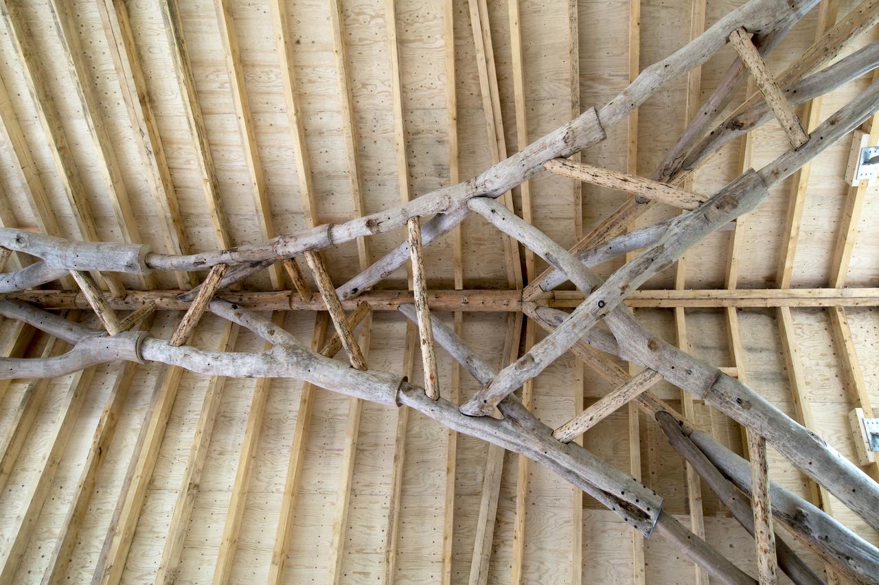
We went on to apply this way of working in projects such as the Woodland Cabin, and others have since replicated the workflow in further studies. The account below returns to the truss itself, where we worked out how to connect a collection of irregular tree forks to a precise building geometry.
It draws on my project portfolio and the paper written with Martin Self for Advances in Architectural Geometry 2016. Each step depends on the next: the survey informs the design, the scans describe the pieces we have, and shared references let us bring the design back to the wood.
Finding forks
Historically, shipbuilders went into the woods looking for curved and branched timbers that suited the parts of a hull. In Hooke Park, we wanted to understand the forms available before deciding exactly how to put them together.
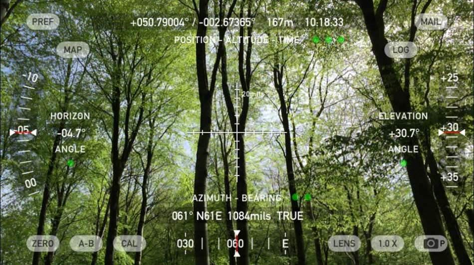
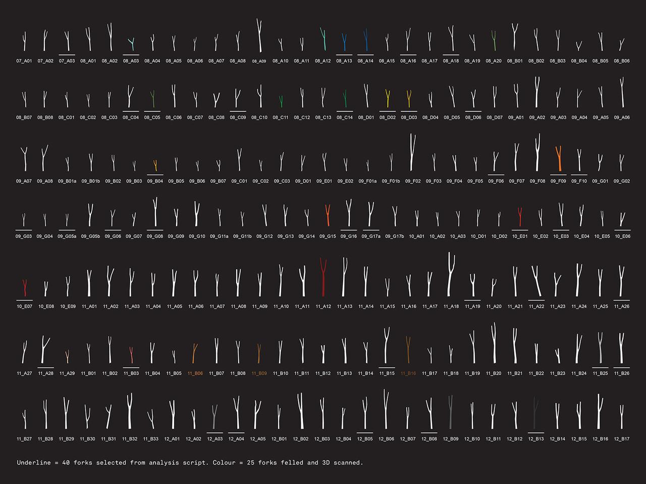
We photographed 204 standing beech forks. Tracing and correcting those photographs gave us approximate outlines; location information allowed us to find the trees again. The survey was detailed enough to compare opening angles and diameters, and to develop a shortlist with input from Arup.
With this shortlist prepared, we returned to the woods with Hooke Park's forester, Christopher Sadd. Some forks were omitted and others added after closer observation. A few trees were ruled out for forestry reasons: their removal could have a negative effect on those around them. Finding useful geometry was only one part of choosing the material.
Twenty-five forks were successfully harvested. Breakages during felling and defects found later continued to affect what could be used. The material available and the design developed together.
A reference shared by model and material
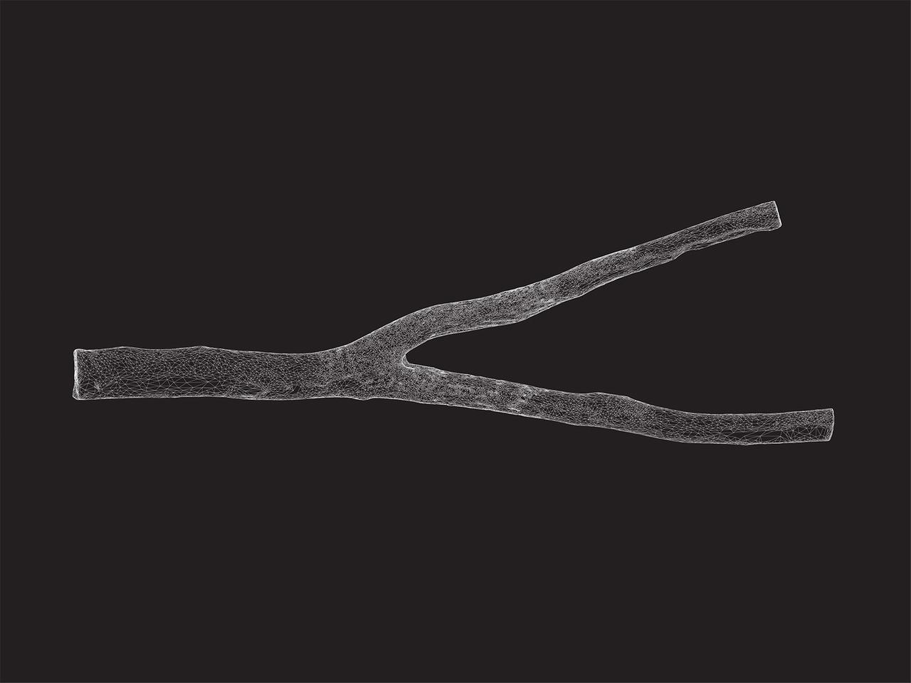
Back in the yard, each fork was recorded through photogrammetry. Sections through its surface mesh provided approximate diameters and centre curves for its three limbs. Those curves made it possible to work with the shape without carrying every surface detail through each calculation.
Three holes drilled into each fork established a local reference system. Recorded in the scan, they defined the relationship between the physical piece and its digital model. Later, those same holes located the fork on its supports in the robot cell.
This was a fundamental consideration throughout: how could we achieve construction precision when the material itself was irregular? Consistent references let us position a piece reliably without needing to know every detail of its surface perfectly.
Organising forks
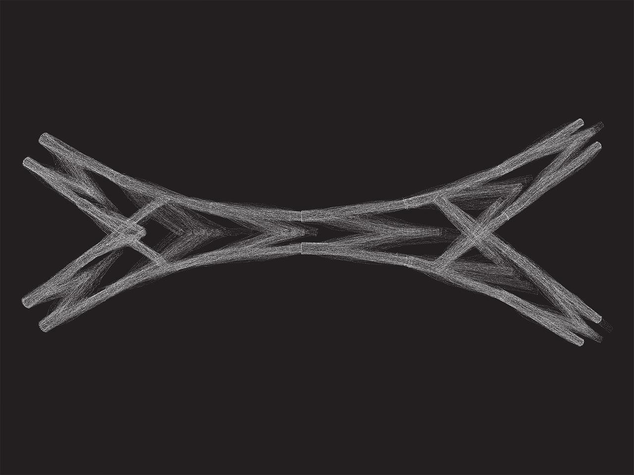
The truss organises twenty forks within a volume designed with their sizes and shapes in mind. A Grasshopper script placed the forks against target curves, allowing them to change position and shuffle within it. We explored arrangements with the engineers, accounting for local diameters, clearances and the connections that would be needed.
The human role remained significant. Some positions were harder to fill than others, so the order of selection mattered. Defects found in otherwise useful forks caused further exchanges as the arrangement was finalised. The script was a way to work with this particular collection of pieces.
Assembling forks
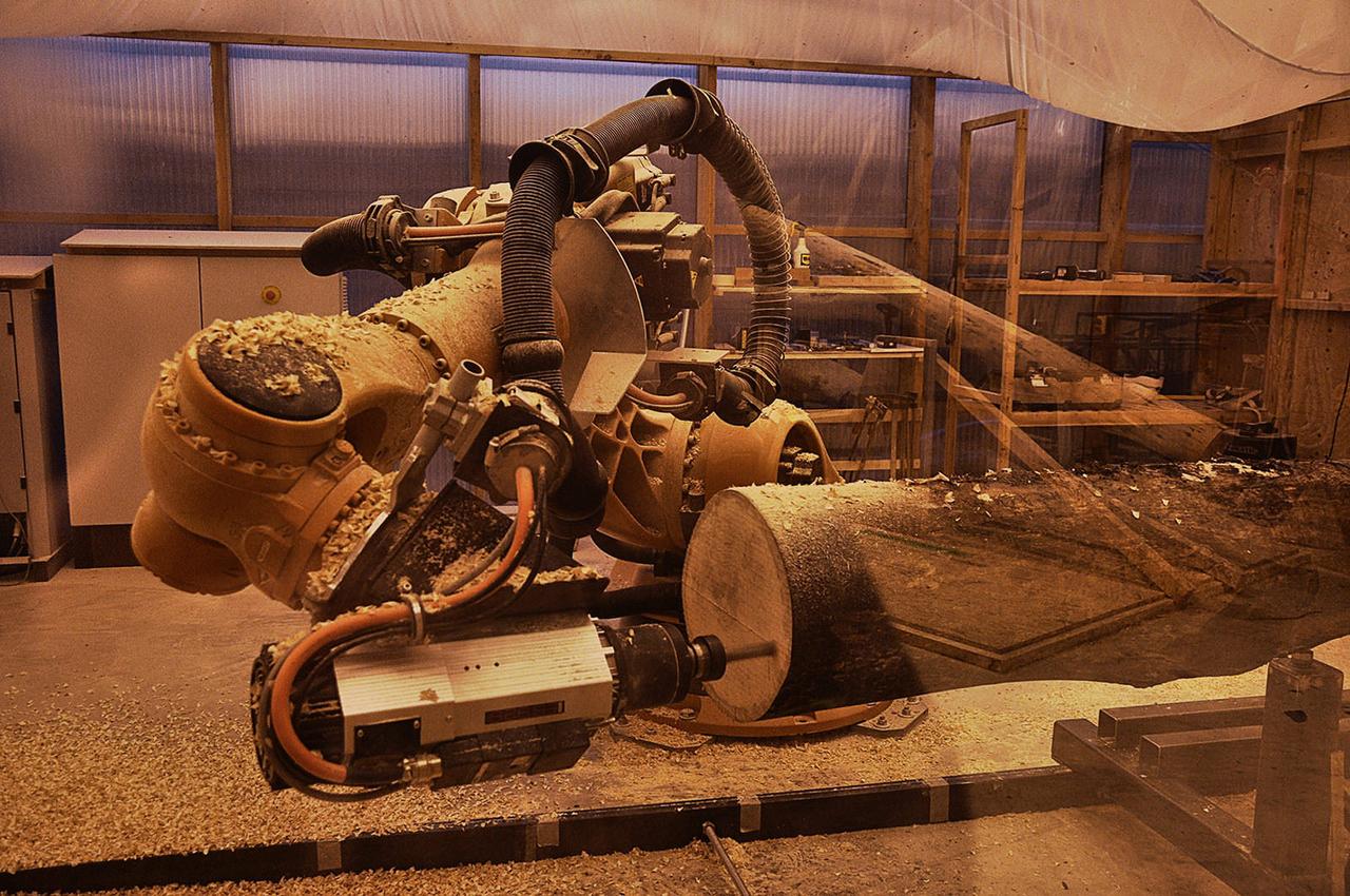
With a final organisation selected, the robotic arm machined connection geometries into each fork to define its relationship to those around it. Cutting volumes extended beyond the expected surface of the wood, allowing for some uncertainty in the scan while keeping the connecting faces precisely positioned.
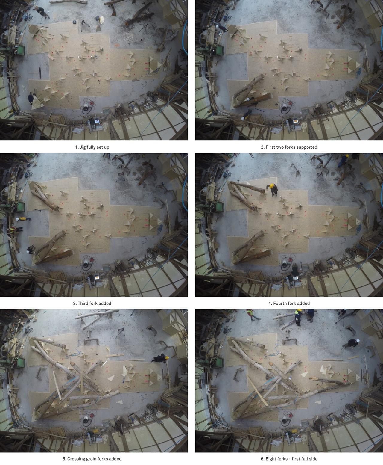
The last machining operations added a second set of three reference holes, this time for assembly. A large jig made from CNC-cut OSB and timber supports allowed us to set out those points in the Big Shed.
All ten forks of one half were loosely positioned before connections were made. Working around the truss with hammers and ratchet straps, the team adjusted the pieces together. With one half complete, the jig was cleared and set up for the other. The two assemblies were eventually moved to site and craned into position.
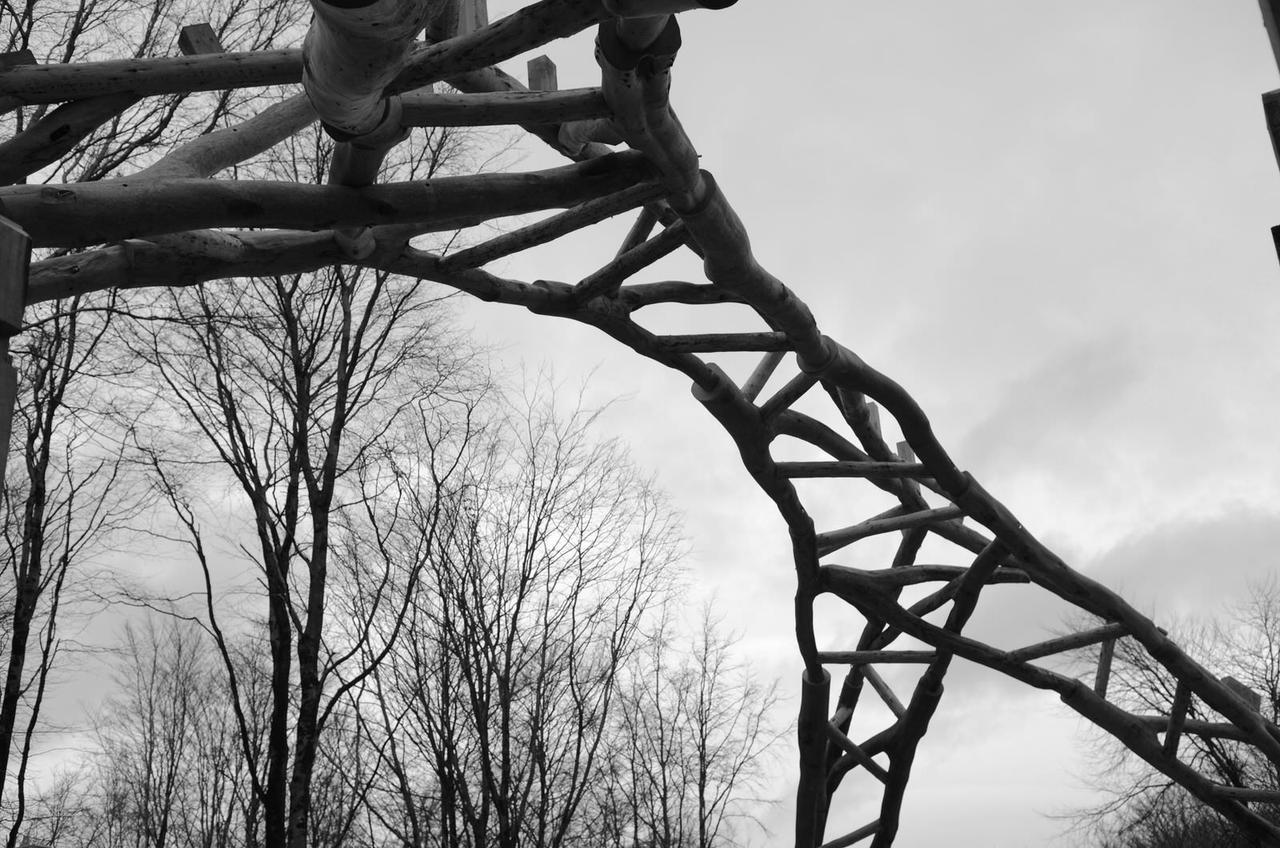
Digital tools and timber framing practices worked together throughout. The scans made the forms available to design; the references carried that design back into the workshop; assembly remained a substantial piece of physical work.
Paper and project
Tree Fork Truss: Geometric Strategies for Exploiting Inherent Material Form, by Zachary Mollica and Martin Self, explains the survey, placement and fabrication methods in detail. Published in Advances in Architectural Geometry 2016.
The project page includes the film, portfolio and full team credits. This was collective work by Design + Make students, tutors, workshop staff, foresters and engineers.
This project advances one part of a wider Ground to Crown approach: finding valuable purposes for more of a tree.
For related methods, see Photogrammetry notes. For other ways of using whole and irregular timber, explore Ground to Crown.
Looking for help with a scan? See my 3D scanning services.